


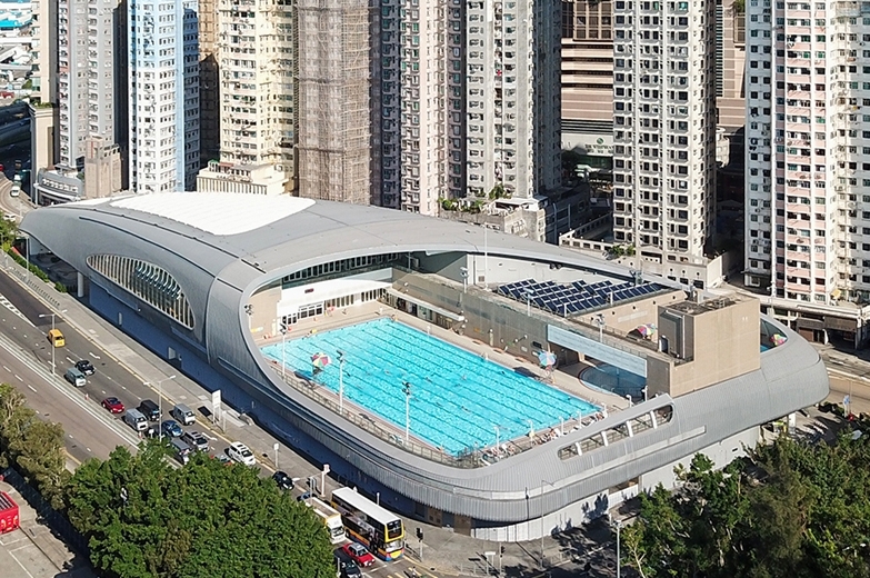
The Kennedy Town Swimming Pool is a public swimming complex in Kennedy Town, Hong Kong. There have been two pools of this name. The first iteration opened in 1974 while the current iteration opened in 2011.
Products been used
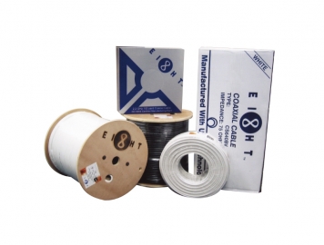
- Cable
- Rack Cabinet

Managing coaxial, fiber optic cable, and digital signals across sprawling campuses or commercial towers? A unified, end-to-end approach removes compatibility gaps, reduces downtime, and cuts procurement chaos. Here is how the pros do it.
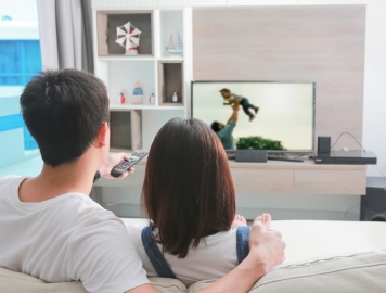
In any large-scale facility — think of a major transport hub like Hactl or a sprawling hotel complex — the first enemy is attenuation. A signal travelling through hundreds of metres of tv cable or coaxial cable loses amplitude, especially at higher frequencies. A high-gain, low-noise amplifier doesn’t just boost the level; it preserves the signal-to-noise ratio. For example, when you have a headend feeding 40+ floors, a masthead amplifier with less than 1 dB noise figure ensures that the tv tuner at the furthest outlet sees a clean picture. Without this stage, you might encounter ghosting, pixelation, or complete loss on digital channels.
We often recommend amplifiers with automatic gain control (AGC) because environmental factors — temperature, cable aging, connector oxidation — can shift signal levels. When you are managing a system that includes both legacy analogue and modern DVB-T2 signals, a flat gain response across 5–2400 MHz is critical. A well-designed amplifier also combats intermodulation distortion. Installers who skip this step often end up debugging intermittent faults that trace back to an under-specified amplifier. For large sites, the amplifier is not a commodity; it is the foundation of the entire network solutions reliability.
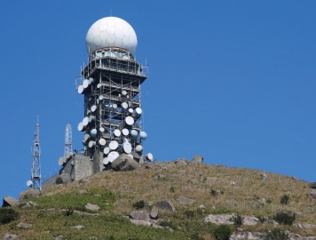
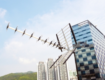
Modern facilities rarely rely on a single signal source. You might have a satellite dish with a quad LNB feeding into a headend, a terrestrial UHF antenna, and an IPTV stream from the building’s fibre backbone. The demodulator stage converts these disparate formats into a common baseband — usually an ASI or IP transport stream. Why does this matter? Because a unified headend simplifies distribution. Instead of running separate fibre optic cable for satellite TV and another coax for terrestrial, a modular demodulator chassis processes all inputs and re-modulates them onto a single coaxial cable or fibre cable infrastructure.
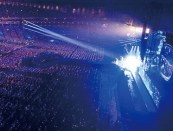
In practice, for a project like kennedy town swimming pool photos — where public areas require consistent TV distribution — a multi-format demodulator receives signals from the satellite LNB and the local antenna, then outputs clean MPTS (Multiple Program Transport Stream). This is exactly where compatibility matters: a mismatch between the LNB local oscillator frequency and the demodulator’s input range can cause total failure. Equipment from experienced integrators like Eight Limited ensures that the demodulator, amplifier, and hdmi splitter or modulator stages are pre-configured to work as one system.
One of the most common questions we hear: “Should I run everything in fibre optic cable or stick with coaxial cable?” The real answer is hybrid. Coaxial cable — especially high-quality RG6 or RG11 — is excellent for last-metre connections. It powers the tv tuner or set-top box through the same cable, and it is robust enough for in-wall installations. But when you need to cover distances over 200 metres or run a trunk line from one building to another, fibre wins. Fibre cable has virtually no signal loss over kilometres, is immune to electromagnetic interference, and can carry enormous bandwidth.
Consider a campus like the Hong Kong International Airport (where Hactl operates). A single fibre optic cable backbone can aggregate hundreds of TV channels, CCTV feeds from ptz camera systems, and data for public address — all on a single strand. Then, at each distribution point, a media converter converts the optical signal back to electrical RF on coaxial cable. This is the principle behind every modern public antenna system and satellite tv system. Without a hybrid design, the cost of copper alone would be prohibitive, and the signal degradation unacceptable.
Transitioning from coaxial to fibre and back requires purpose-built hardware. Eight Limited provides media converters and SFP optical transceivers that handle RF-over-fibre with minimal latency. For example, a typical CATV optical transmitter takes the RF signal from the headend (47–1000 MHz) and converts it into a 1310 nm or 1550 nm optical signal. On the receiving end, the optical receiver converts it back. The key specification to look for is the link budget: the difference between the transmitter output (dBm) and the receiver sensitivity. For long-distance runs (5 km or more), 1550 nm optics with EDFA amplification are standard.
In a real-world deployment, we have seen projects where using a cheap media converter caused a 3 dB signal loss — which translates to a 50% reduction in power. That difference can break a satellite tv system’s ability to lock transponders. Eight Limited’s transceivers are specified to work with om3 fiber (multimode) for intra-building links and single-mode for campus backbones. The fibre optic cable itself must be terminated with quality connectors — a poorly polished connector can introduce more loss than 500 metres of cable. That is why the integration of fibre cable with proper transmission equipment is part of the one-source promise.
The headend is where the magic happens. In a typical 42U server rack or standard cabinet, you house the demodulators, modulators, amplifiers, optical transmitters, and power supplies. A modular chassis system allows hot-swappable cards — so if you need to add a new channel or a different modulation format (QAM, DVB-T, or ATSC), you simply insert a card without rewiring the whole system. For a facility that expects to grow (a hotel adding a new wing, a hospital expanding a ward), this modularity saves months of redesign.
Many operators overlook the thermal management inside a wall mount cabinet or a server cabinet. When you pack 20+ cards, each dissipating 15–30 watts, internal temperatures can exceed 60°C — which shortens capacitor life and drifts oscillator frequencies. A proper rack layout includes blanking panels, front-to-rear airflow, and sometimes an integrated fan tray. A heavy duty rack that can support deep chassis (like those for dvr recording or network solutions switches) is non-negotiable.
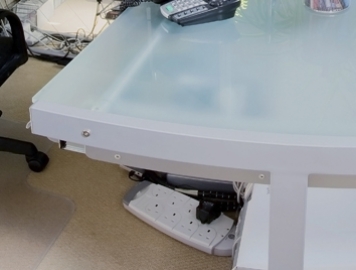
“Spaghetti cabling” is the leading cause of service outages during maintenance. Every patch cable, hdmi cable, speaker wire, and coaxial cable should be dressed neatly using horizontal managers and D-rings. For the video matrix or hdmi switcher that routes AV signals to multiple zones, colour-coded cables reduce human error. Power redundancy means dual PSUs (power supply units) fed from separate circuit breakers. In a facility like a hospital or control centre, an extension socket daisy-chain is not acceptable. A dedicated power distribution unit (PDU) with surge protection and monitoring is fitted inside the outdoor cabinet or indoor rack.
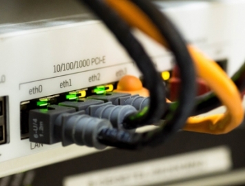
We also recommend installing a patch panel for all fibre and ethernet cable terminations. Instead of running a long rj45 cable directly from a switch, terminate it on a patch panel and use short patch cable to connect. This makes troubleshooting and reconfiguration faster. For AV signals, a hdmi splitter or an hdmi matrix simplifies distribution to multiple displays. All these components — from the tv cable to the patch panel — need to be tested together to guarantee impedance matching.
Here is a scenario we encounter regularly: an integrator buys a demodulator from brand A, an amplifier from brand B, and fibre optic cable from brand C. On paper, they all meet the specs. In the field, the demodulator outputs a signal level that overloads the amplifier’s input. Or the frequency response of the amplifier has a 2 dB ripple at a critical channel. Or the coaxial cable impedance is 75 ohms, but the extension socket or connector has a 50-ohm impedance causing reflections. These gaps cause endless callbacks.
The solution is one-source engineering. When every component — from the headend to the fibre termination box — is selected, tested, and guaranteed by a single provider with 30 years of local experience (like Eight Limited), interoperability is not left to chance. The network solutions are validated for cat8 performance, the dvr and ptz camera integration follows Hikvision’s SDK guidelines, and the public antenna system meets OFCA requirements.
Eight Limited’s approach is rooted in their motto: “Infinite Possibilities.” They stock thousands of SKUs — from Comway fusion splicer machines for field terminations to wall mount cabinet enclosures, rj45 keystone jacks, and even speaker wire for paging systems. But more importantly, they offer pre-configured kits. For a recent project involving a large housing estate (similar to the infrastructure needed for kennedy town swimming pool photos), they delivered a headend rack that was pre-wired, pre-tested, and labelled. The installer just had to connect the coaxial cable drops and the fibre cable backbone.
They also provide technical documentation, signal budget calculations, and on-site support. When you call Eight Limited, you are not ordering an hdmi splitter in isolation; you are getting a subsystem that includes the necessary lnb, media converter, and cable management accessories. This reduces procurement fragmentation. For any project where uptime is critical — hospitals, Hactl cargo terminals, or government buildings — this end-to-end responsibility is invaluable.
Before buying a single component, you must calculate the signal budget. Start by measuring the signal level at the antenna or satellite dish (in dBµV). Subtract the loss of every metre of coaxial cable, every connector, every splitter. For a 20-storey building, a typical drop cable run might be 50 metres. Coaxial cable like RG6 loses about 5 dB per 100 metres at 800 MHz. Add 2 dB for each connector. Then factor in the splitter loss (3.5 dB for a 2-way, 7 dB for a 4-way). The amplifier gain must compensate for the total loss and still deliver 60–70 dBµV at the outlet.
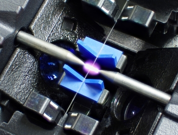
For fibre sections, calculate the optical link loss: fibre optic cable attenuation (0.35 dB/km for single-mode, 0.5 dB/km for OM3 at 850 nm) plus connector loss (0.3 dB per mated pair). If you are using a Comway fusion splicer, the splice loss should be under 0.05 dB. A site survey also identifies where to place active equipment — avoid placing a wall mount cabinet in a boiler room where heat exceeds 45°C.
Follow this proven order:
1. Mount the headend rack — Use a standard rack or heavy duty rack bolted to the floor. Install the power distribution and grounding.
2. Install demodulators — Connect the lnb and antenna feeds. Set the channel plans. Verify the ASI/IP output on a dvr or monitor.
3. Connect the headend amplifier — Use short coaxial cable jumpers with high-shielding. Set gain so that output is ~90 dBµV.
4. Run the fibre backbone — Pull fibre optic cable through conduit, avoiding sharp bends (bend radius ≥ 10× cable diameter). Terminate with fusion splicer or mechanical connectors.
5. Install distribution racks — Each floor or zone gets a wall mount cabinet or small rack containing a return-path receiver and splitter network.
6. Test every outlet — Use a field strength meter to verify levels. Check that each tv tuner locks all expected channels.
Commissioning is where many projects fail. Use this checklist:
·✔ Measure signal level at the furthest outlet: must be within 55–75 dBµV for digital.
·✔ Check MER (Modulation Error Ratio): > 30 dB for 64-QAM, > 36 dB for 256-QAM.
·✔ Verify optical power at receiver: should be within -8 to +2 dBm (depending on receiver).
·✔ Test hdmi splitter and hdmi cable runs for HDCP compliance.
·✔ Confirm ptz camera control (RS-485/RS-422) works through the same coaxial cable if using coaxitron.
·✔ Document all patch cable and fibre patch panel connections.
·✔ Run a 48-hour stress test on the headend with all channels active.
Stop sourcing tv cable from one vendor, fibre optic cable from another, and headend gear from a third. Eight Limited delivers fully integrated headend and transmission packages — from amplifier to patch panel, from hdmi switcher to coaxial cable. Pre-tested as a system, backed by 30 years of Hong Kong infrastructure expertise.
 (852) 2413 2222
 (852) 2411 3000
 Tender Sales Manager: Mr. Tam (852) 9496 5891 / Product sales Manager: Mr. Tsang (852) 6131 6550
 info@eightgroup.com
 No.18, 4/F., Thriving Industrial Centre, 26-38 Sha Tsui Road, Tsuen Wan, Hong Kong
(852) 3904 3308
(852) 9040 3214 (message only)
customerservice@eightgroup.com
No.23, 4/F., Thriving Industrial Centre, 26-38 Sha Tsui Road, Tsuen Wan, Hong Kong
No.18, 4/F., Thriving Industrial Centre, 26-38 Sha Tsui Road, Tsuen Wan, Hong Kong
(852) 3904 3308
(852) 9040 3214 (message only)
customerservice@eightgroup.com
No.23, 4/F., Thriving Industrial Centre, 26-38 Sha Tsui Road, Tsuen Wan, Hong Kong