


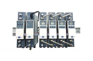
Features
AT420 UHF TV DUAL Channel Amplifiers
- TV channel amplifiers tunable in UHF range
- SAW filters provide a high selectivity processing of digital and analog channels
- Each section has a built-in AGC system and independent regulator of output level
- Built-in indicators and push buttons allow operatively to set required parameters
- DIN rail or wall mounting
- Robust die-cast housing
MA400 Multiband System Amplifier
- FM, BIII & DAB and UHF inputs
- High output level
- Built-in gain controls
- DIN rail or wall mounting
- Robust die-cast housing
UP410S Power Supply
- Modular power supply with integrated RF combiner
- Switch-mode technology
- Short circuit and overload protected
- Robust die-cast housing
Specification
AT420 UHF TV DUAL Channel Amplifiers RF Input
| Sections | 2 | ||
| Tuning Range of Channels | 470 ~ 862 MHz | ||
| TV Standard #1 | analog (G, K, I, NZ) | ||
| DVB-T* / DTMB | |||
| Channel Bandwidth | Analog (G, K, I, NZ) | 8 MHz | |
| DVB-T* / DTMB | 8 MHz | ||
| Level / Impedance | Analog (G, K, I, NZ) | 60-85 dBμV/75 Ω | |
| DVB-T* / DTMB | 50-80 dBμV/75 Ω | ||
| Frequency Range of RF Distribution | 47-862 MHz | ||
| Loop Through Gain | 0 ± 1.5 dB | ||
| Return Loss | >12 dB |
RF Output
| Level / Impedance, Typical | Analog (G, K, I, NZ) | 90 dBμV /75 Ω | |
| DVB-T* / DTMB | 85 dBμV/75 Ω | ||
| MER of DVB-T Signal | DVB-T* / DTMB | ≥ 36 dB (input signal MER 38 dB) | |
| Frequency Range of RF Combining | 47 ~ 2150 MHz | ||
| DC Pass Through | 0.3 A | ||
| Combining Through Loss Terr/SAT | 1.5/2.5 dB | ||
| Level Adjustment Range #1 | 0 ~ -10 dB by 1 dB step | ||
| Return Loss | ≥10 dB |
General
| Noise Figure | Less than 7 dB | ||
| Selectivity, Typical #1 | 40 dB, ±1.25 MHz from 8 MHz bandwidth border | ||
| Offset #2 | ±1 MHz by 0.25 MHz step | ||
| Spurious Signals Level | ≤ -60 dB | ||
| Mirror Channel Selectivity | ≥ 60 dB | ||
| Flatness of Channel Bandwidth, Typical | ± 1.5 dB | ||
| Connector / Impedance | F type / 75 Ω | ||
| DC Feeding for External | 12V 0.1A max. | ||
| Current Consumption #3 | 12V 0.45A | ||
| Operating Temperature Range | -10 °C ~ +60 °C | ||
| Dimensions / Weight (packed) | 36 x 198 x 107.5 mm / 0.9 kg |
MA400 Multiband System Amplifier
| Gain | FM (88-108 MHz) | 30 dB | |
| VHFIII (174-260 MHz) | 30 dB | ||
| UHF (470-862 MHz) | 30 dB | ||
| Number of Inputs | 3 | ||
| Noise Figure | < 7 dB; UHF < 5 dB | ||
| Maximal Output Level | VHF 116 dBμV; | ||
| IMD3=60 dB (DIN45004B ) | UHF 118 dBμV | ||
| Gain Control | Attenuator | 0 ~ -15 dB | |
| Switch | 0/-10 dB | ||
| Return Loss | > 10 dB | ||
| Connector / Impedance | F type / 75 Ω | ||
| DC Feeding for External (Total) | 12V 0.1 A max. | ||
| Current Consumption #3 | 12V 0.48 A | ||
| Operating Temperature Range | 0 ~ +50˚C | ||
| Dimensions / Weight (packed) | 36x198x107.5 mm / 0.9 kg | ||
UP410S Power Supply
| Input Voltage | 187~250 V~ 50/60 Hz | ||
| Output Voltage, Current | 12V 4.5 A max. | ||
| Power Consumption | 65 W max. |
RF Combiner
| Frequency Range | 47~2400 MHz | ||
| Insertion Loss | 4 dB at 862 MHz | ||
| 6 dB at 2400 MHz | |||
| Isolation | ≥ 20 dB | ||
| Return Loss |
≥ 20 dB at 862 MHz ≥12 dB at 2400 MHz |
Other
| Operating Temperature Range | 0 ~ +50˚C | ||
| Dimensions | 48 x 198 x 107.5 mm | ||
| Weight (packed) | 0.97 kg |
#1 Software control
#2 The offset is used for fine tuning of the channel frequency response
#3 Without external DC loading
#3 Without external DC loading
Download Documents
Related Products